The schematics for each electrical system used on our robot are included below. Power was supplied using two 7.2V NiMH batteries for our motors with a 6.2V buck converter for our electromagnet. Another 7.2V NiMH battery was used to power the Tiva. We used to Tiva's power distribution to provide 5V and 3.3V to the sensing circuits. All boards contained a 100 uF bypass capacitor, and each chip had a 0.1 uF bypass capacitor associated with it.
POWER DISTRIBUTION
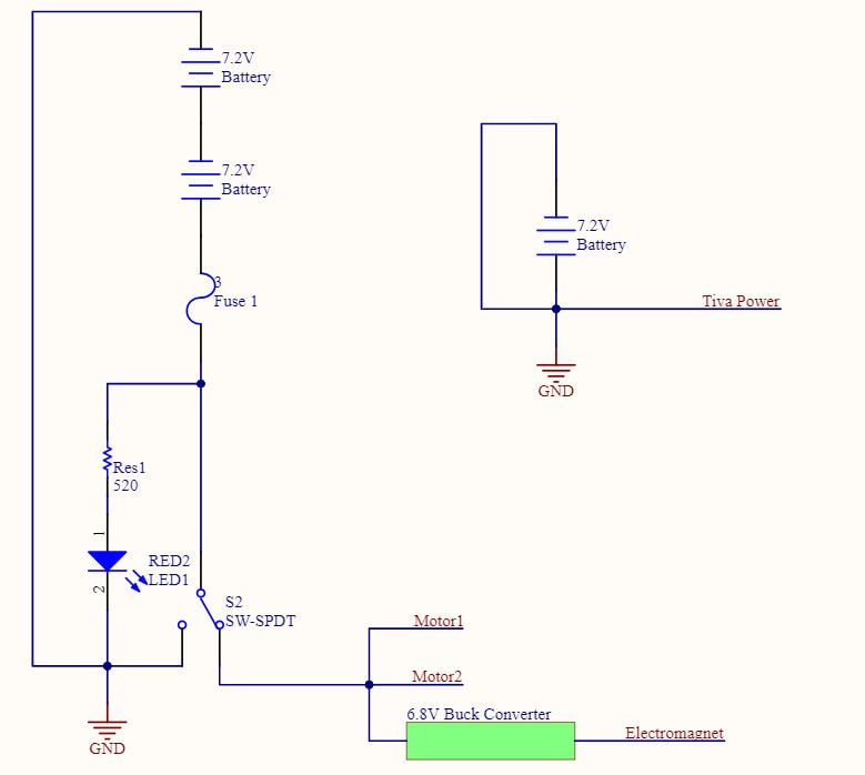
This power distribution circuit routs the voltage from two 7.2V batteries to the two motors and a 6.2V Buck converter which powers the electromagnet. The circuit includes a Kill Switch for turning the motors and the electromagnet off while debugging. It also includes a 5A fuse in line with the batteries to prevent sustained over-current in case of a short. The fuse was sized to account for the normal operation of the motors used in our system.
ELECTROMAGNET
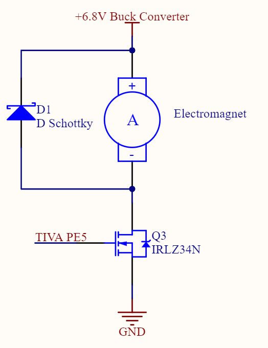
This electromagnet circuit routs voltage from the Buck converter to power the two electromagnets. A kickback diode is implemented as per the device’s datasheet to eliminate sudden voltage spikes due to the induction of the magnet.
CORPORATE LED
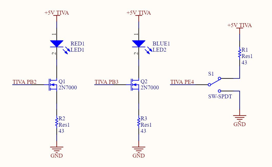
Two identical circuits are used to communicate to spectators the corporate association of the robot by lighting up a large LED. The team uses a physical switch to communicate to the Tiva which corporation the robot is meant to serve.
IR DETECTION
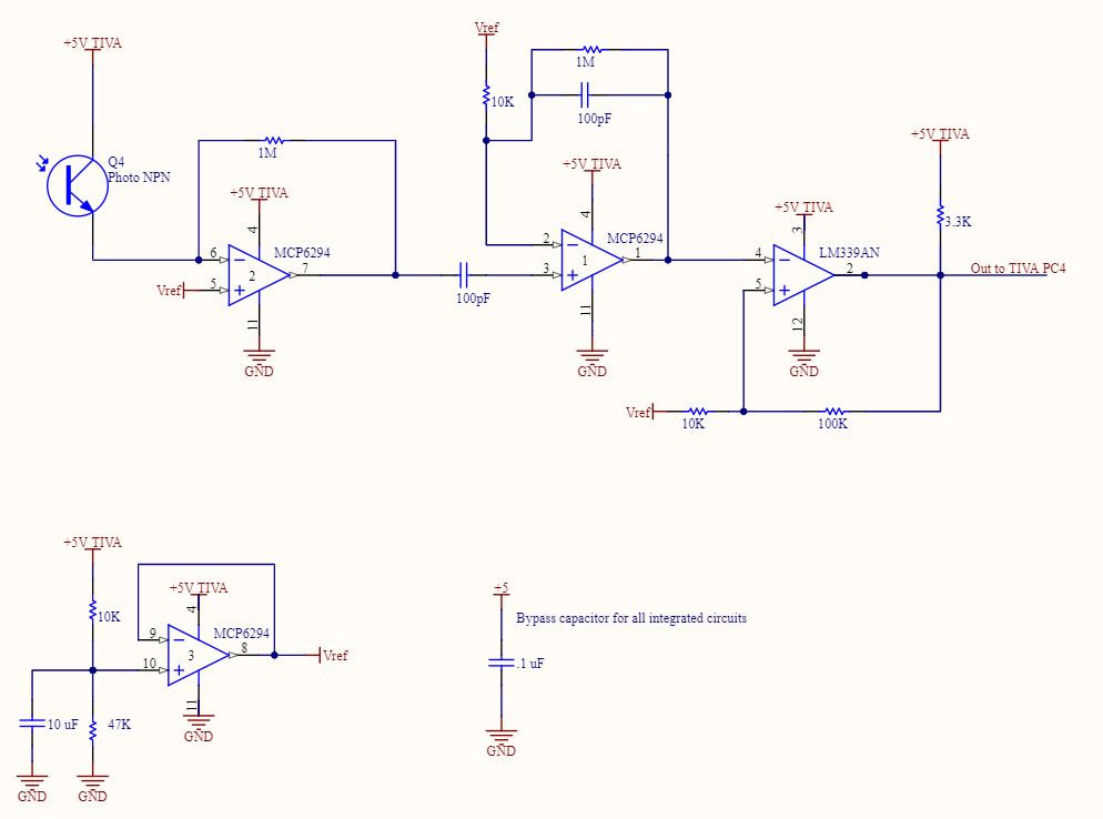
Signal from an IR detector is conditioned through a trans-resistive stage, a gain stage and a Schmitt trigger.
TAPE SENSOR
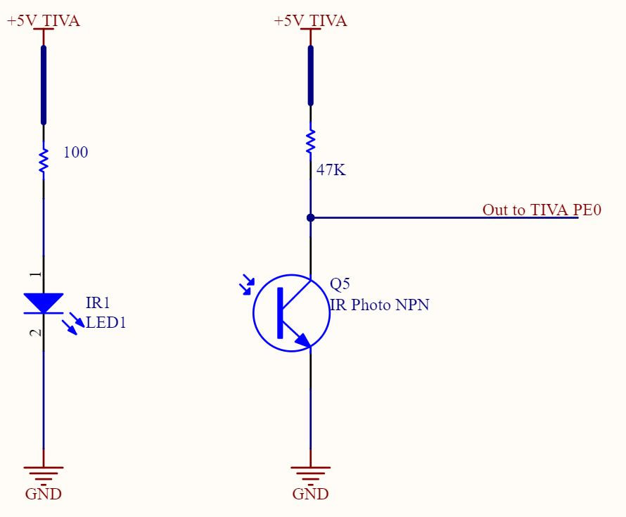
A tape sensor is mounted on tier 1 of the robot to detect when a MINER is ready to be captured by the electromagnets. Sensor signal is fed directly into the Tiva.
MOTORS
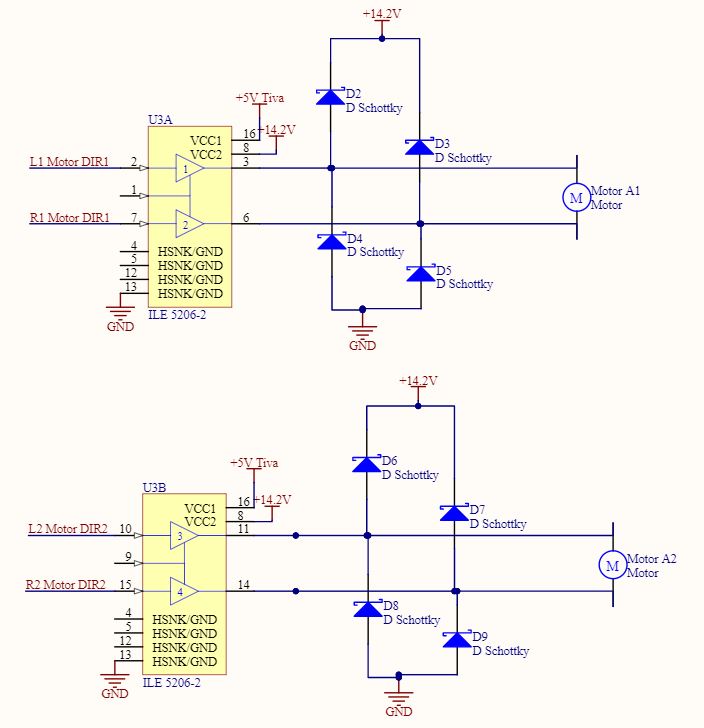
Our two motors are controlled by encoders and driven by a TLE 5206.
TIVA PINOUT
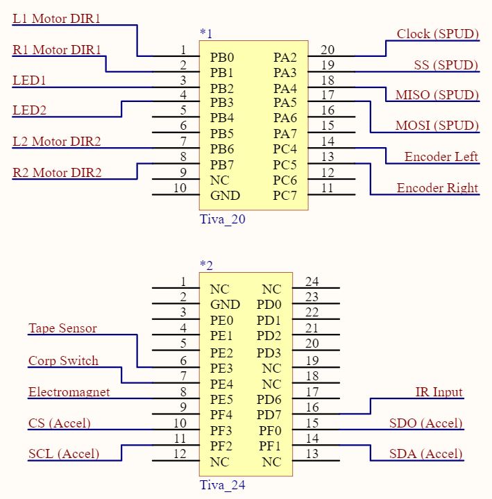
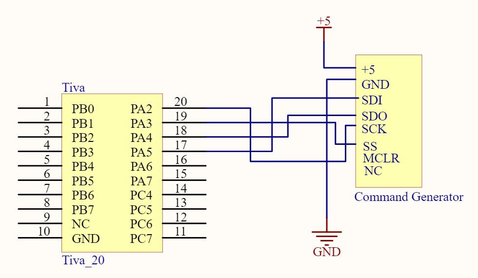
Our robot was controlled by the Tiva’s 20-pin and 24-pin ribbons.
COMMAND GENERATOR