Mechanical overview
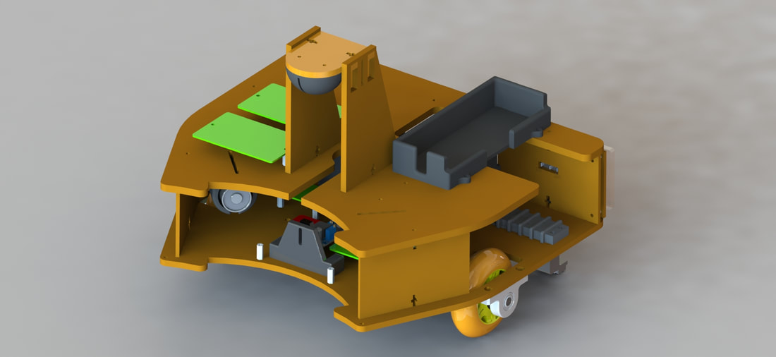
For this project, we decided to take a very CAD oriented approach. Before a single piece of duron was cut, board soldered, or 3D print made, we laid out the entire design in SolidWorks. Not only did this allow us to get a good idea of size and layout but we were also able to plan far into the future, taking into account power source mounting and wire routing to minimize noise as a function of mechanical design.
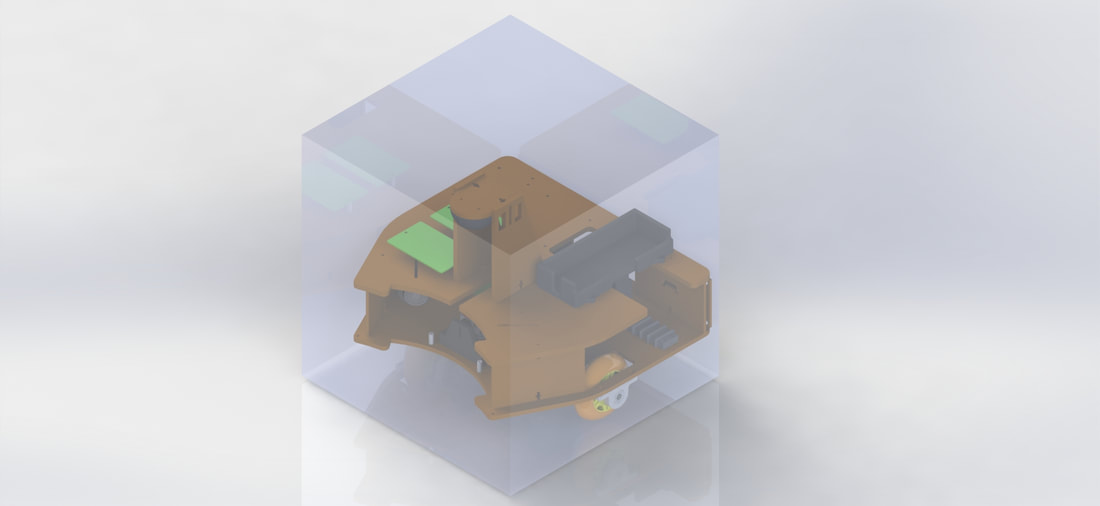
The whole assembly was required to fit within a 30cm box. In keeping with the method outlined above, we constrained our design in CAD early on to the box shown below.

In general overview, we settled on a tiered design, separating sensing elements from drive elements in an effort to preserve stable, reliable signals. In order to facilitate this design, we opted to use a captured nut system as seen below.

This system allowed for strong, repeatable connections that could be easily disassembled if work was needed on a lower tier that was more difficult to access.
tier 0: Drivetrain
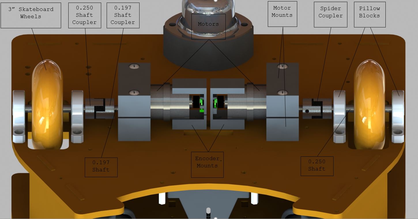

As can be seen above, the drivetrain was designed with robustness as a priority and compactness secondary. We opted for robust design because of the level of testing we knew this robot would go through. Between running into walls, being flipped over for maintenance, and even being placed on and off our workbench over and over, a mechanical failure later on down the road would be a huge roadblock. To prevent these potential issues, we moved forwards with a design that included 2 pillow blocks per wheel as well as bulky motor mounts that both clamped the motor casings and bolted onto the drive face. A spider coupler was used to give compliance to the system so that torsional forces would not be directly transferred to the motor shaft. It would also allow for slight misalignment of the drive shafts. Pololu encoders were adapted to fit the encoder shafts of the provided motors.
The only creative mechanical implementation here was the use of slots to under-constrain the motors and encoder mounts. As mentioned before, the encoders used in this project were adapted to fit the provided motors. Accordingly, pieces did not fit together exactly as anticipated. Because the magnet needed to be in a very specific location to trigger ticks in the encoder, the slots allowed for significant axial adjustment. Radial adjustment was achieved through shimming using washers.
Tier 1: under the hood
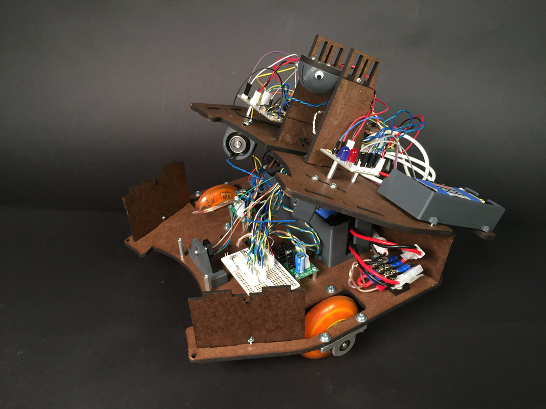
The first tier was designed to control the majority of the power distribution as well as serving as a way-station for data lines like the tape sensor and encoders. The half protoboard seen above simply took lines that needed to go up to the second tier and consolidated them into wire bundles. By doing this, it allowed us to have a single access port going from the first tier to the second tier which improved our wire management greatly. It also made it easier to quickly unplug molexes and detach the second tier to do work on the first tier.
This is also where the majority of the batteries are stored. It is important to notice the orientation of our wheels and roller bearing which exist in an imbalanced tripod orientation. This means that the front of our robot is cantilevered out from the wheelbase. We settled on a design like this to prevent high centering from having two, symmetrical roller bearings. We also wanted to have the axis of our wheels go through the center of volume of our robot. This facilitated turning “on a dime”. All of this is relevant to the batteries because they were used as ballast. Our batteries were significantly heavier than everything else on our robot, so by placing them in the back on top of the roller bearing, we used them to prevent the robot from tipping towards the cantilevered front.
As previously mentioned, this tier also housed power distribution boards and buck converters which provided power to the motors and electromagnets. By isolating these high current components on this tier, we prevented noise in our sensing elements.
tier 1.5: Electromagnets
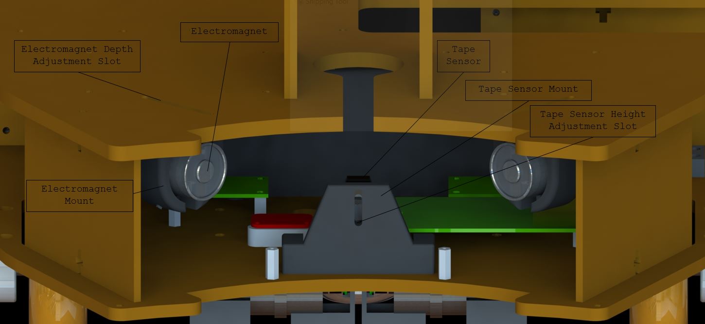
Front View
Located on the bottom of the second tier (hanging into the first tier) were the electromagnets. These were placed at a specific height to interact with the ferrous strip wrapped around the rim of the MINERs These electromagnets were also mounted in slots to under-constrain them and increase their flexibility. The slots were oriented radially from the center of the miner when latched to maximize orthogonal contract and thus create a stronger, more reliable connection.
Like the electromagnets, the tape sensor (which is very finicky and only works with surfaces a certain distance away) was fix in a slotted mount for versatility.
tier 2: The brain
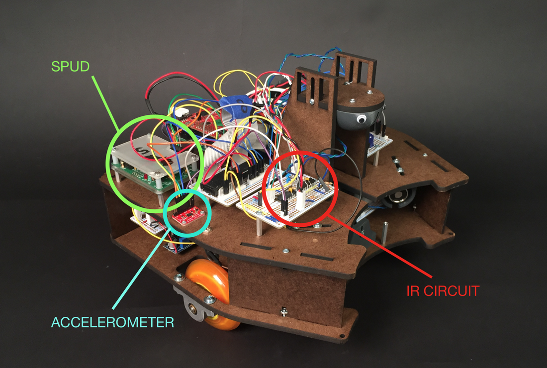
The second tier is where all of the hardware logic was implemented. Here, a completely isolated IR circuit, the connection-sensitive accelerometer, and the necessary SPUD all had direct access to the TIVA ribbon cables. By having the short connections, we assured the reliability of the data that we were receiving from each component.
tier 2.5: Ir tower
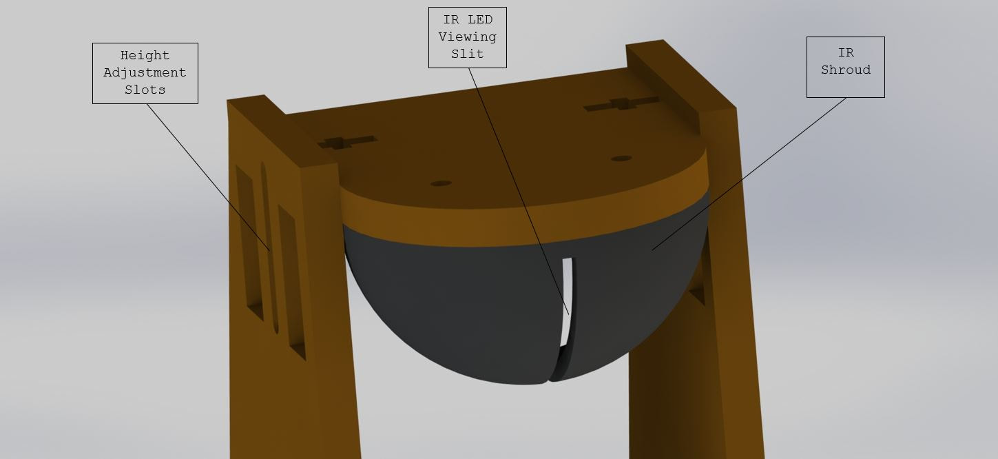
Like the electromagnet, the IR tower was designed with the MINER in mind. The height of the mounted IR phototransistor depended on the height of the IR LEDs on the MINERs. Once again, this system was under-constrained for maximum versatility. A vertical slit filter was 3D printed to facilitate the detection of the MINERs. Without exact vertical alignment between our senser and the IR beacons on the MINER, the relative height changes as a function of the distance away the robot is from the MINER. By opening the slit in the vertical direction, we allowed for detection regardless of our distance from the MINER. Furthermore, by limiting view in the rotational direction, we increased the accuracy of our sensor since light would only reach the phototransistor when the narrow slit was in line with the beacon.
